CAD is Complete, Time to Build!
Hopper Design Update
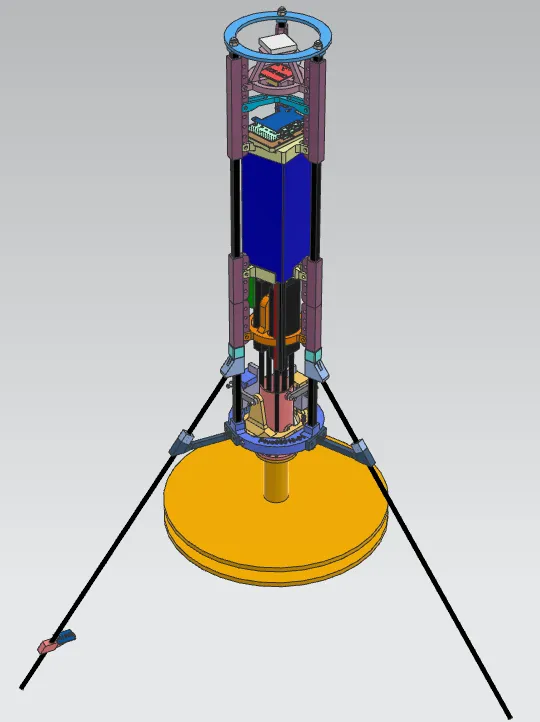
After multiple iterations, the design for the hopper is finally laying flat! Here’s some basic info about the platform:
Aerodynamics
Due to the extremely low speeds this vehicle will be operating at, I chose to forgo any aerodynamic features. There is no nose cone, no body tube, etc. These features would just add weight while not providing any meaningful benefits. This is more drone than rocket. An additional benefit is that the lack of a body tube/fuselage allows for easy access to all internal components.
Component Mounting
I wanted to design for flexibility and allow components to be added, removed, or rearranged down the road. Gluing, drilling, and screwing components directly into the CF rod would eliminate any flexibility—if I wanted to change a component location, I would need to start from scratch and get a new rod!
Instead, I glued mounting rails to the rods. Now, I can mount components to the rails and then add, remove, or rearrange components as much as I desire! If I decide to redesign a component mount, I just have to reprint it and screw it back onto the mounting rail. Although it adds weight, the flexibility it provides down the road makes it worth the cost.
Electronics
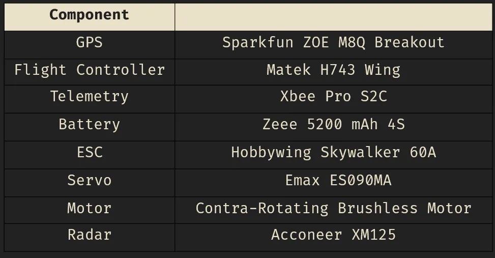
I am attempting to build this using entirely off-the-shelf components—no custom electronics. Although I have designed custom electronics for past projects (and may still have to for this one), I want this to be as simple and reliable as possible. So, I am using components with plenty of documentation.
Something interesting I’m trying is to use an off-the-shelf flight controller, the Matek H743Wing, rather than something custom. Most people in the space lean towards a custom PCB, but since this flight controller utilizes an STM32 microcontroller, I believe I can write custom firmware for it—allowing me to create a custom flight controller but on a platform with proven reliability.
Parts List
Sizing
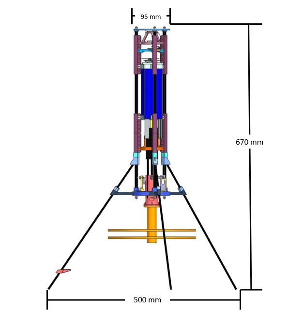
Initially, this vehicle was twice as tall! I planned to make it using two sections of CF rods instead of just one. This was mainly an attempt to spread out the mass along the length of the vehicle, thus increasing the MOI and making it a little bit easier to control.
However, that arrangement ended up well over my mass budget—the motor only produces ~1.3 kg of thrust, and the elongated vehicle was 1.1 kg. Since this vehicle will utilize thrust vectoring, I’m aiming for a thrust-to-weight ratio around 1.5:1, accounting for thrust losses when the motor is pivoted.
The final vehicle dimensions are shown below. This new design should have an all-up weight of ~900 g.
Overall Platform Dimensions
Now that the CAD is completed, it’s time to start printing and assembling! I’ll be back with more updates once that process is complete.
For more frequent project updates, follow along on X!